The 2010 Chrysler Town & Country manual provides essential guidance for owners, detailing features, maintenance, and troubleshooting for this popular minivan model.

Overview of the Vehicle
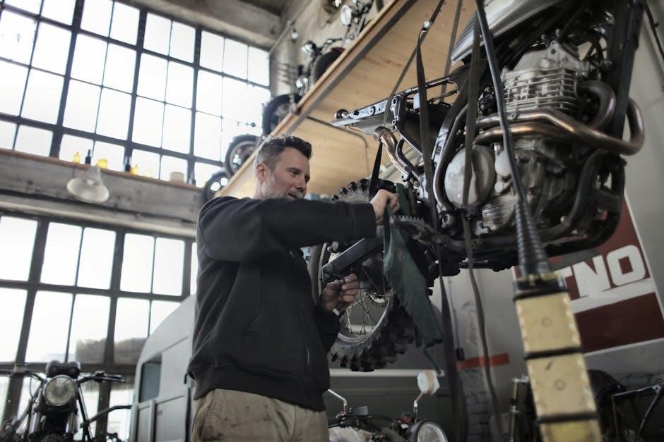
The 2010 Chrysler Town & Country stands as a cornerstone of the minivan segment, renowned for its family-focused design and versatile functionality. As a leading name since the 1980s, it offers a spacious interior and a comfortable ride, catering to the needs of modern families. This model year continues the tradition of providing practical features and a blend of convenience and style.
Chrysler consistently refined the Town & Country, and the 2010 version benefits from ongoing improvements in design and specifications. Owners can expect a vehicle equipped with features designed for both everyday commuting and long road trips. Understanding the vehicle’s capabilities, as outlined in the owner’s manual, is crucial for maximizing its potential and ensuring a safe and enjoyable driving experience. The manual details everything from basic operation to more complex maintenance procedures.
Importance of the Owner’s Manual
The 2010 Chrysler Town & Country owner’s manual is an indispensable resource for all vehicle owners. It serves as a comprehensive guide to understanding the vehicle’s features, operation, and maintenance requirements. Chrysler Group LLC explicitly states its right to make changes to designs and specifications, making the manual a vital source for the most current information applicable to your specific vehicle.
Beyond basic operation, the manual details critical safety features and procedures. It also outlines a preventative maintenance schedule, helping owners avoid potential issues and maintain optimal performance. Accessing information about Technical Service Bulletins (TSBs), as referenced in online forums, is also facilitated through understanding how to navigate the manual’s resources. Properly utilizing this document ensures responsible vehicle ownership and longevity.

Understanding the 2010 Town & Country Features
The 2010 Town & Country, a leading minivan since the 1980s, offers versatility and luxury, with models ranging from sedans to convertibles.
Engine Specifications and Performance
The 2010 Chrysler Town & Country primarily featured a 3.8L V6 engine, delivering around 197 horsepower and 262 lb-ft of torque. This engine provided adequate power for everyday driving and family hauling. While not a performance vehicle, the Town & Country focused on smooth and reliable operation.
Fuel economy was typical for the class, averaging around 17 MPG city and 25 MPG highway. The engine was designed for longevity and ease of maintenance, contributing to the vehicle’s overall practicality. Chrysler also offered a more powerful 4.0L V6 option in some trims, boosting horsepower to approximately 251 and torque to 265 lb-ft, enhancing towing capacity and acceleration. Regular maintenance, as outlined in the owner’s manual, was crucial for optimal engine performance.

Transmission System (Focus on Manual Options ‒ if any, otherwise automatic)
The 2010 Chrysler Town & Country exclusively came equipped with a 6-speed automatic transmission; A manual transmission option was not available for this model year, aligning with the minivan segment’s focus on convenience and ease of driving. This automatic transmission was designed to deliver smooth gear changes and optimize fuel efficiency.
The transmission featured AutoStick functionality, allowing drivers some control over gear selection for situations like towing or navigating hilly terrain. Regular transmission fluid checks and changes, as detailed in the owner’s manual, were vital for maintaining its performance and preventing costly repairs. Proper maintenance ensured reliable operation and extended the transmission’s lifespan, contributing to the vehicle’s overall dependability.
Interior Features and Comfort
The 2010 Chrysler Town & Country prioritized passenger comfort and versatility. The interior boasted Stow ‘n Go seating, allowing second-row seats to fold completely into the floor, creating a spacious cargo area. Available features included leather upholstery, heated front seats, and a rear entertainment system with a DVD player, enhancing long journeys.
Climate control was multi-zone, ensuring personalized comfort for all occupants. The dashboard incorporated user-friendly controls and a sound system. Safety features like multiple airbags and advanced security systems were standard. The manual details operation of these features, alongside cleaning and care instructions to maintain the interior’s quality and appearance throughout ownership.

Key Sections of the 2010 Town & Country Manual
The manual comprehensively covers safety, operation, maintenance schedules, and fluid specifications – vital information for owners of the 2010 Chrysler Town & Country.
Safety Features and Operation
The 2010 Town & Country prioritizes passenger safety with a suite of features detailed in the owner’s manual. This includes information on the proper use of seatbelts for all occupants, emphasizing their critical role in minimizing injury during a collision. The manual also explains the operation of the vehicle’s airbag system, including supplemental restraint system (SRS) indicators and precautions.
Furthermore, it provides guidance on utilizing child safety seats correctly, adhering to manufacturer’s instructions and legal requirements. Drivers will find detailed explanations of anti-lock brake system (ABS) functionality and emergency braking procedures. The manual also covers essential safety systems like traction control and stability control, outlining their operation and limitations. Understanding these features and operating the vehicle responsibly, as outlined in the manual, is paramount for a safe driving experience.
Starting and Operating Procedures
The 2010 Chrysler Town & Country manual provides a comprehensive guide to safely starting and operating the vehicle. It details the proper ignition sequence, including key positions and associated system checks. The manual explains the function of various dashboard indicators, alerting drivers to potential issues. It also covers essential controls like steering, braking, and acceleration, emphasizing smooth and controlled operation.
Detailed instructions are provided for utilizing features like the automatic transmission, including gear selector positions and driving modes. The manual also outlines procedures for using the parking brake, ensuring vehicle security. Furthermore, it explains the operation of power windows, door locks, and climate control systems, enhancing driver and passenger comfort. Following these procedures ensures optimal performance and longevity of the vehicle.
Maintenance Schedule and Procedures
The 2010 Chrysler Town & Country manual outlines a detailed maintenance schedule crucial for preserving vehicle reliability. It categorizes services by mileage intervals – typically every 30,000 miles or two years, whichever comes first – covering essential checks and replacements. Procedures include oil and filter changes, tire rotations, brake inspections, and fluid level checks.
The manual specifies the correct fluid types and capacities for various systems, ensuring proper operation. It details how to inspect belts and hoses for wear, and provides guidance on replacing the air filter and cabin air filter. Following the recommended schedule prevents costly repairs and maintains optimal performance. Regular maintenance, as described, is vital for maximizing the lifespan of your Town & Country.
Fluid Specifications and Capacities
The 2010 Chrysler Town & Country manual meticulously lists required fluid specifications and capacities for optimal vehicle performance. Engine oil requires 5W-20 or 5W-30, with a 6.6-quart capacity. The automatic transmission necessitates ATF+4 fluid, holding approximately 9.5 quarts. Power steering fluid should be MS-9227, needing around 0.75 quarts.
Coolant requires a 50/50 mix of ethylene glycol and distilled water, with a system capacity of roughly 12.5 quarts. Brake fluid must meet DOT 3 specifications. Knowing these precise requirements prevents damage from incorrect fluids. The manual emphasizes using only approved fluids to maintain warranty coverage and ensure component longevity, safeguarding your Town & Country’s systems.

Troubleshooting Common Issues
The 2010 Chrysler Town & Country manual assists in diagnosing frequent problems, covering electrical faults, engine hiccups, and transmission concerns for swift resolution.
Electrical System Problems
The 2010 Chrysler Town & Country manual details troubleshooting for common electrical issues. These can range from simple fixes like blown fuses – the manual provides fuse box diagrams – to more complex problems involving the vehicle’s wiring harness. Owners should consult the manual for guidance on diagnosing issues with the power windows, door locks, and interior lighting.
The manual also addresses potential problems with the vehicle’s charging system, including a failing alternator or battery. It outlines procedures for jump-starting the vehicle safely and checking battery connections. Furthermore, the manual may reference Technical Service Bulletins (TSBs) related to specific electrical faults experienced in the 2010 model year, offering potential solutions identified by Chrysler engineers. Always prioritize safety when dealing with electrical components.
Engine Performance Issues
The 2010 Chrysler Town & Country manual offers guidance on diagnosing engine performance problems. Common issues include rough idling, decreased fuel efficiency, and a loss of power. The manual details how to check for vacuum leaks, inspect spark plugs, and assess the condition of the air filter – a simple replacement task outlined within.
It also provides information on interpreting the vehicle’s check engine light, advising owners to use an OBD-II scanner to retrieve diagnostic trouble codes. These codes can pinpoint the source of the problem, such as a faulty oxygen sensor or catalytic converter. Referencing relevant Technical Service Bulletins (TSBs) is crucial, as Chrysler may have identified specific engine-related concerns for the 2010 model year and provided recommended fixes.

Transmission Concerns (Automatic Focus)
The 2010 Chrysler Town & Country manual addresses potential automatic transmission issues. Owners might experience slipping gears, harsh shifting, or delayed engagement. The manual stresses the importance of checking the transmission fluid level and condition – discoloration or a burnt smell indicates a problem. Regular fluid changes, adhering to the maintenance schedule, are vital for longevity.
Troubleshooting steps include inspecting for leaks and examining the transmission control module (TCM) for error codes. The manual advises against attempting complex repairs without professional assistance. Consulting Technical Service Bulletins (TSBs) is recommended, as Chrysler may have issued specific guidance for addressing common transmission concerns in the 2010 Town & Country, potentially involving software updates or component replacements.

Specific Maintenance Tasks
The 2010 Chrysler Town & Country manual details routine upkeep like filter replacements and battery care, ensuring optimal vehicle performance and longevity for owners.
Air Filter Replacement
Referencing the 2010 Chrysler Town & Country manual, replacing the air filter is a straightforward maintenance task crucial for engine health. Locate the air cleaner housing, typically a black plastic box; Disengage the retainers securing the air inlet duct, as outlined in the BODY section of the manual. Carefully remove the duct for access.
Once accessible, release the clips or screws holding the air filter cover. Lift the cover and remove the old filter, noting its orientation for correct installation of the new one. Ensure the new filter seats properly within the housing, and replace the cover, securing it with clips or screws. Reconnect the air inlet duct, engaging the retainers firmly. Regular air filter replacement, as per the maintenance schedule, optimizes airflow and fuel efficiency.
Cabin Air Filter Replacement
According to the 2010 Chrysler Town & Country manual, the cabin air filter cleans air entering the vehicle’s ventilation system. Its location varies, often behind the glove compartment. Begin by emptying the glove compartment and disconnecting any associated tethers. Release the retaining tabs or screws securing the glove compartment door, allowing it to fully swing down.
Locate the cabin air filter access panel, usually a rectangular cover. Remove the cover to reveal the filter. Note the airflow direction arrow printed on the filter frame for correct re-installation. Gently slide out the old filter and insert the new one, ensuring the arrow points in the correct direction. Replace the access panel, glove compartment door, and reconnect any tethers. This improves air quality inside the vehicle.
Battery Maintenance and Replacement
The 2010 Chrysler Town & Country manual emphasizes regular battery inspection for corrosion around terminals. Clean corrosion with a baking soda and water solution, then rinse and dry thoroughly. Ensure the battery cable connections are tight. For replacement, disconnect the negative terminal first, then the positive, to avoid short circuits.
Remove the battery hold-down clamp. Lift the old battery out carefully, avoiding spills. Install the new battery, securing it with the hold-down clamp. Connect the positive terminal first, then the negative. Verify connections are secure. Proper disposal of the old battery is crucial; recycle it at an authorized facility. Maintaining a healthy battery ensures reliable starting and electrical system function.

Technical Service Bulletins (TSBs) for 2010
The 2010 Town & Country manual benefits from checking TSBs for known issues and recommended fixes, improving vehicle performance and reliability.
Identifying Relevant TSBs
Locating applicable Technical Service Bulletins (TSBs) for your 2010 Chrysler Town & Country is crucial for addressing potential vehicle concerns proactively. Several online resources compile these bulletins, often searchable by vehicle year, model, and specific symptom. Websites dedicated to Chrysler vehicles, alongside official Chrysler resources (though access may vary), are excellent starting points.
When searching, utilize keywords describing the issue you’re experiencing – for example, “transmission slipping,” “electrical malfunction,” or “air conditioning failure.” Carefully review the TSB details to confirm if the described problem matches your vehicle’s symptoms. Pay attention to the affected vehicle identification number (VIN) ranges specified in the TSB, ensuring your vehicle falls within the applicable range. Remember that TSBs offer recommended repair procedures, not mandatory recalls, but can provide valuable diagnostic and repair information.
Applying TSB Information
Successfully utilizing Technical Service Bulletins (TSBs) requires careful consideration. While TSBs detail recommended repair procedures, they aren’t a substitute for proper diagnostic skills. Always verify the TSB’s information aligns with your vehicle’s specific condition before commencing any repairs.
If you’re undertaking the repair yourself, ensure you possess the necessary tools, expertise, and safety precautions. The TSB will outline specific parts required; confirm their availability before starting. If you’re relying on a mechanic, share the TSB with them to ensure they’re aware of the recommended solution. Remember, a TSB is a guide, and a skilled technician may adapt the procedure based on their assessment. Document all work performed, referencing the TSB number for future reference.

Resources for Repair and Information
Online forums and communities, alongside repair manuals and literature, offer valuable support for 2010 Town & Country owners seeking assistance and guidance.
Online Forums and Communities
Engaging with online Chrysler forums, like the Chrysler Forum – Chrysler Enthusiast Forums, proves incredibly beneficial for 2010 Town & Country owners. These platforms host a wealth of knowledge shared by fellow enthusiasts and experienced mechanics. Users frequently discuss common issues, share repair tips, and offer solutions to troubleshooting problems specific to this model year.
These communities often archive Technical Service Bulletins (TSBs), providing insights into known manufacturer fixes. The forums facilitate a collaborative environment where owners can ask questions, post photos of issues, and receive tailored advice. Accessing these resources can save time and money compared to solely relying on professional diagnostics, fostering a supportive network for maintaining your vehicle.
Repair Manuals and Literature
Comprehensive repair manuals are indispensable resources for 2010 Chrysler Town & Country owners undertaking DIY maintenance or repairs. Platforms like eBay.com offer a vast selection of repair manuals and related literature, catering to various skill levels. These manuals provide detailed diagrams, step-by-step instructions, and technical specifications crucial for accurate servicing.
Beyond general repair guides, accessing official Chrysler service documentation – often available through subscription services or specialized retailers – offers the most precise information. These resources detail factory procedures, wiring schematics, and diagnostic flowcharts. Investing in quality literature empowers owners to confidently address mechanical issues, understand vehicle systems, and ensure repairs are performed correctly, extending the lifespan of their Town & Country.